Materials Science
Editor's pick
Research Article
Experimental study on the rheological characteristics and viscosity-enhanced factors of super-viscous heavy oil
By Yang Chen, Jin Luo, Meiyu Zhang, Minglan He
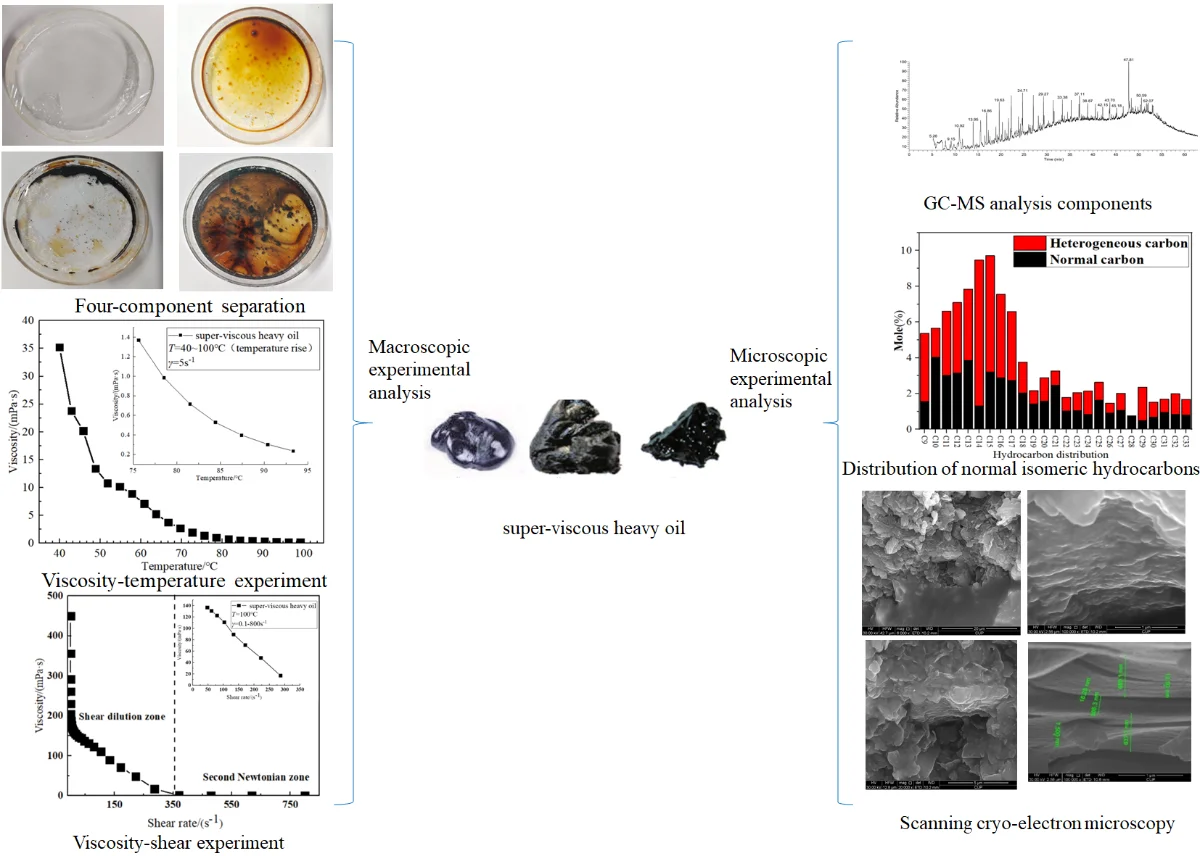
To reveal the viscosity-enhanced mechanism of super-viscous heavy oil and improve the recovery rate of super-viscous heavy oil, the four components, elemental composition, rheological properties, and effects of asphaltenes and resin on the viscosity of super-viscous heavy oil from well TH12434 in Tahe Oilfield, China have been analyzed from macro and microscopic perspectives by Anton Paar rotational rheometer, gas chromatography-mass spectrometry and scanning cryo-EM to solve the problems of poor fluidity and high asphaltene content. The experimental results showed that in the temperature range of T= 40-100°C, the viscosity of super-viscous heavy oil decreases sharply from 352000 mPa∙s to 1620 mPa∙s, and the super-viscous heavy oil exhibits clear thermo-sensitivity. With T= 100°C and shear rate ranging from γ= 0-800 s-1, the viscosity of super-viscous heavy oil decreases sharply from 45000 mPa∙s to 956 mPa∙s, and the oil sample shows typical pseudoplasticity. The baseline of super-viscous heavy oil analysis by gas chromatography shows too high, and more than 80 % of super-viscous heavy oil compounds have a matching degree of less than 70 % with standard compounds, indicating that the super-viscous heavy oil had poor heterogeneity and many impurities. It is observed by scanning cryo-EM that the micromorphology of super-viscous heavy oil is large granular, strong continuity, asphaltene micromorphology presents an obvious layered structure, the layer spacing is 637.7 nm, and its asphaltene molecules form an order-like or crystal-like association structure through several unit sheet layers, resulting in high viscosity of super-viscous heavy oil. Based on the analysis results of the influencing factors of the viscosity of super-viscous heavy oil, a theoretical basis for the selection of viscosity reduction technology for super-viscous heavy oil the efficient exploitation in Tahe Oilfield, China could be provided.
November 7, 2023
Industrial Engineering
Most cited
Research Article
A conversion guide: solar irradiance and lux illuminance
By Peter R. Michael, Danvers E. Johnston, Wilfrido Moreno
December 4, 2020
Applied Physics
Most cited
Research Article
Experimental kinematic analysis of an intermittent motion planetary mechanism with elliptical gears
By Alexander Prikhodko
September 30, 2020
Applied Physics
Most cited
Research Article
Experimental analysis of cutting force during machining difficult to cut materials under dry, mineral oil, and TiO2 nano-lubricant
By I. P. Okokpujie, L. K. Tartibu
December 13, 2021
Applied Physics
Most cited
Research Article
Experimental and finite element approach for finding sound absorption coefficient of bio-based foam
By L. Yuvaraj, S. Jeyanthi, Lenin Babu Mailan Chinnapandi
September 30, 2019
Public Health
Liquid and Gaseous Energy Resources
Research Article
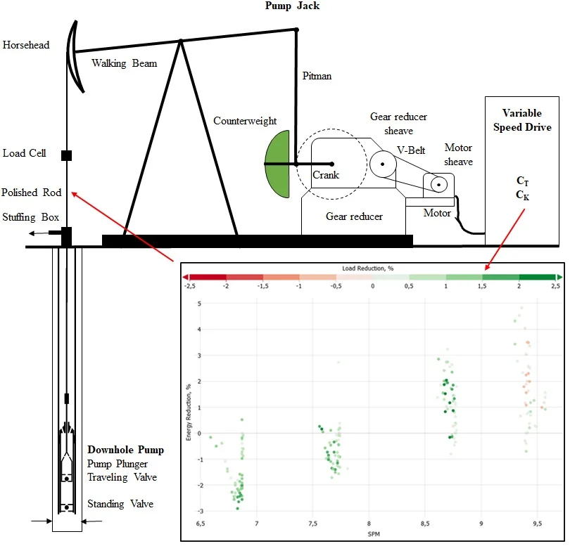
Sucker rod pump frequency-elastic drive mode development – from the numerical model to the field test
A frequency-elastic drive mode for a sucker rod pumping system is introduced to reduce its polished rod peak loads and the total energy consumption. Numerical modeling and an extensive field test verify the concept. The frequency-elastic drive mode is a software solution for variable speed drive systems, which can be applied in the controller and does not require any hardware adjustments. The novel drive mode adjusts the set frequency, sent by the controller to the frequency converter, depending on the actual power requirements. An increase in power consumption results in a reduction of the set frequency, which is proportional to the power consumption increase. A reduction in power consumption results in the opposite effect to achieve a similar pumping speed as for regular operation. The frequency-elastic drive mode is simulated by a numerical model, which covers the entire pumping system. An extensive field test was performed to verify the concept and the numerical model. The simulation and the field test have confirmed the concept of the frequency-elastic drive mode and quantified its saving potential. The evaluation of the field test has shown that the energy-saving potential can reach five percent. In addition, a peak polished rod load reduction of up to three percent was seen. At the tested pumping system the frequency elastic drive mode under optimized parameters yields the best results in terms of total energy savings in the pumping speed range between 7 to 10 strokes per minute. A downhole system efficiency increase was seen for any pumping speed. The numerical model matches the field test data and allows the performance prediction of the novel drive mode for changed parameters and wellbore configurations without extensive field testing. The novelty of the presented paper is the concept of the frequency-elastic drive mode, which is a pure software solution for variable speed drive sucker rod pumping systems. The holistic model includes the entire pumping system and matches the field test data at remarkable accuracy.
June 21, 2021
Industrial Engineering
Research Article
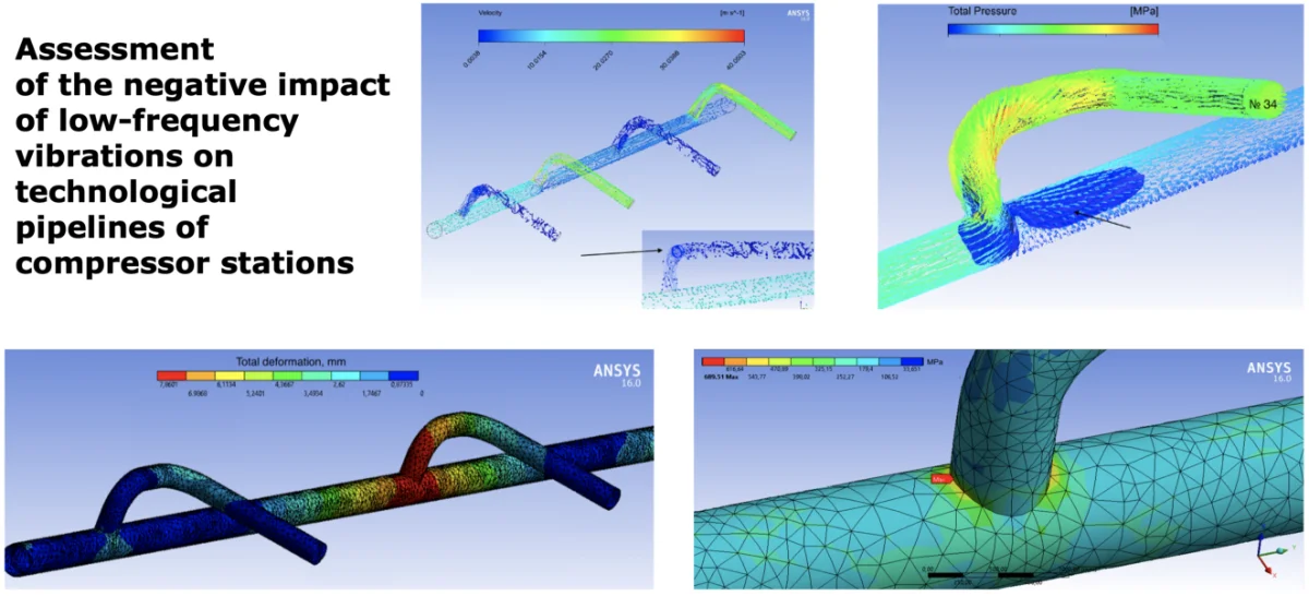
Assessment of the negative impact of low-frequency vibrations on technological pipelines of compressor stations
The intensive development of gas transport and compressor manufacturing aimed at increasing the unit capacities of gas pumping units, creating high-flow centrifugal compressors, increasing the productivity of compressor shops has led to the appearance of fundamentally new problems in the diagnosis of industrial pipelines. The reasons for premature failure of piping manifold of gas pumping stations can be associated with both high static voltage in the pipelines and a high level of vibration. The main reasons for the increased vibration of the technological pipelines of the centrifugal compressor can be significant disturbing forces of the gas flow, coincidence of the natural frequencies of the pipeline system elements with frequencies of the disturbing forces, low dynamic stiffness of the pipeline- support system or a combination of the above conditions. The most effective method for studying problems such as low-frequency vibrations is the combination of engineering means for calculating dynamic processes and the results of measurements of the parameters of these processes in real systems and operating modes of the compressor stations. The hypotheses of the occurrence of low-frequency vibrations in pipelines are considered during the study, the acoustic properties of the process piping, and the resonant vibrations conditions are calculated. A computer model was created in the ANSYS Workbench software in order to consider the loading conditions for process piping. Based on Gazprom company standard 2-2.3-324-2009, an algorithm is proposed that is of practical importance for engineers of plant diagnostics operating gas transmission equipment. It is proposed to combine the performance of vibroacoustic studies and computing modeling with the determination of trends in the technical condition of the system for the analysis of changes in vibro-parameters. As a result of the work, direct measurements of the vibrodiagnostic specialists of the operating compressor station were compared with the obtained modeling data. Some methods were proposed to reduce the impact of operating conditions and design of the process piping on unacceptable low-frequency vibrations.
June 25, 2021
Industrial Engineering
Research Article
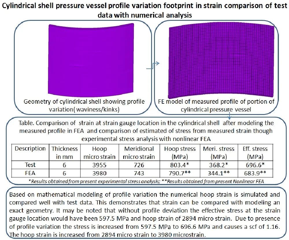
Cylindrical shell pressure vessel profile variation footprint in strain comparison of test data with numerical analysis
The strain comparison of a pressure vessel made of HSLA 15CDV6 in a cylindrical shell membrane region in a pressure test is discussed in this paper. Non-linear finite element analysis (FEA) of thin-walled cylindrical pressure vessels has been carried out using ANSYS. Hoop strain obtained from FEA is not compared well with the pressure test data at the membrane location of the cylindrical shell where the strain gauge is mounted. So to explain the reasons for the difference in strains at the membrane region, the profile of the cylindrical shell at strain gauge region has been measured. The 3D FEA of the cylindrical region with the measured profile is performed. It is found that with measured profile the FEA is giving the strain close to measured strain in the hoop direction. This leads to the increase in strain and stress as having been demonstrated through mathematical modeling in the deviated profiles variations of cylindrical shells. Therefore, the stresses in the deviated region are greater than those that would exist in an undeviated cylindrical shell, which reduces the margin of safety with respect to the yield strength of the material and causes stress concentration. The details of the stress analysis carried out including the effect of measured 3D profile variation are discussed in this paper.
December 23, 2021
Industrial Engineering
Research Article
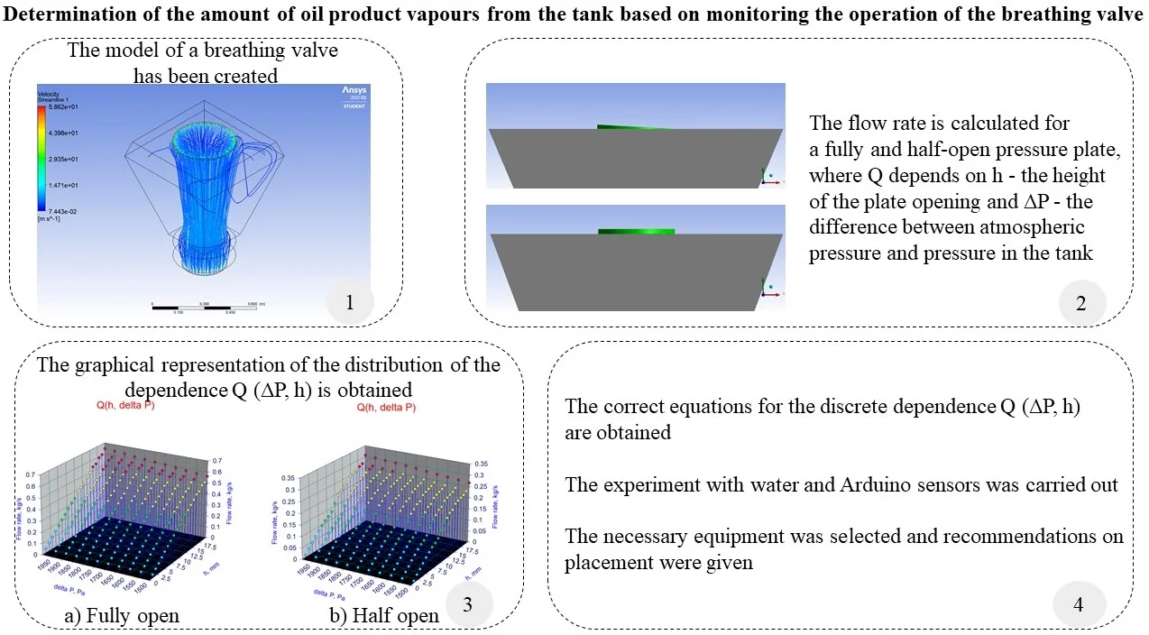
Determination of the amount of oil product vapours from the tank based on monitoring the operation of the breathing valve
The development of methods for calculating losses of oil and petroleum products vapours from the tank has been going on for a long time. Systems that allow for more accurate calculations are also being developed along the way. In each country, and sometimes in each company, there are their own methods for determining the loss of light hydrocarbon fractions from losses from the tank through the breathing valve. In addition, losses are divided into “working losses” and “standing losses”. In each technique, there are both pros and cons. The most characteristic disadvantage of each technique is its applicability only to the conditions in which it was developed, due to the presence of correction coefficients. This article proposes a new technique for determining the loss of hydrocarbons vapours from the tank through the breathing valve, both from “working losses” and from “standing losses”. In the course of the work, formulas were obtained for calculating the flow rate Q∆P,h through the breathing valve, which depends on the degree of opening of the pressure plate and overpressure. An experiment was conducted, instrumentally proving the application of the developed methodology. And also, the equipment is selected and recommendations on its installation and use are given.
June 30, 2022
Industrial Engineering
Liquid and Gaseous Energy Resources
Devoted to transportation of liquid and gaseous energy resources: hydrocarbons, crude oil, oils, petroleum, water, hydrogen, biofuel
APC
Free of charge
Best of Theme
Most cited
Research article
May 7, 2021
Modelling and mitigation of drone noise
By John Kennedy, Simone Garruccio, Kai Cussen
Most cited
Research article
January 22, 2021
Design of low-cost wireless noise monitoring sensor unit based on IoT concept
By Maja Anachkova, Simona Domazetovska, Zlatko Petreski, Viktor Gavriloski
Most cited
Research article
June 29, 2020
Nondestructive microparticle analysis method
By Vadim Rybin, Semyon Rudyi, Olga Kokorina
Most cited
Research article
June 30, 2022
The vibration of a thermoelastic nanobeam due to thermo-electrical effect of graphene nano-strip under Green-Naghdi type-II model
By Hamdy M. Youssef, Abdullah A. Al Thobaiti
You might also like
Most downloaded
Research Article
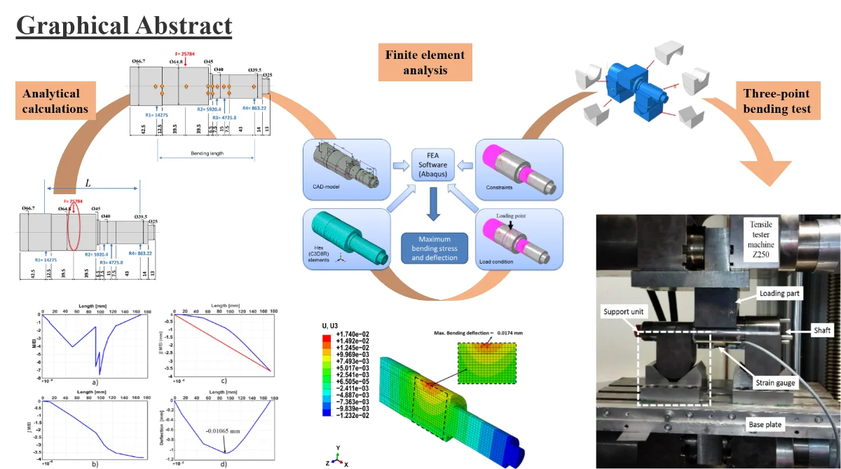
FE analysis and experimental determination of a shaft deflection under three-point loading
By Bernd Engel, Sara Salman Hassan Al-maeeni
Increasing industrial demand for new products including advanced production technology leads to substantial natural resources consumption. Furthermore, huge environmental pollution and emerging environmental legislation motivate the machine tools industry as one of the major resource consumers on a global scale to develop methods for more sustainable use of the Earth's resources. Machine tools re-engineering concerning design and failure analysis is an approach by which outdated machines are upgraded and restored to like-new machines. To evaluate the mechanical failure of the used machine components and to ensure their reliable future performance, it is essential to make material, design, and surface investigations. In this paper, an experimental approach based on the principle of a three-point bending test is presented to evaluate the shaft elastic behavior under loading. Moreover, finite element analysis and numerical integration method are used to determine the maximum linear deflection and bending stress of the shaft. Subsequently, a comparison between the results is made. In conclusion, it was found that the measured bending deflection and stress were well close to the admissible design values. Therefore, the shaft can be used again in the second life cycle. However, based on previous surface tests conducted, the shaft surface needs re-carburizing and refining treatments to ensure the reliable performance of the surface.
September 24, 2018
Applied Physics
Most downloaded
Research Article
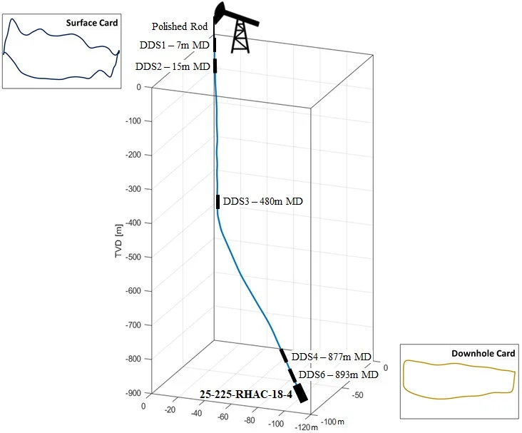
Sucker rod pump downhole dynamometer card determination based on a novel finite element method
By Patrick Eisner, Clemens Langbauer, Rudolf Fruhwirth
An advanced dynamic finite element model is presented that diagnoses the downhole pump performance of sucker rod pumping systems, applicable for any pumping conditions and equipment used. The results are compared to downhole measurements and other evaluation techniques. Buckling is an undesirable phenomenon occurring in sucker rod pumping. It essentially depends on the plunger load, which is a function of time and typically not measured but evaluated by diagnostic tools. Existing diagnostic tools exhibit specific limitations that reduce their applicability and output quality. This paper introduces a diagnostic tool, which can predict the rod string's stress field and its movement not only at the pump plunger but all along the rod string. Moreover, this tool can account for the interaction between rod guides and tubing as well as rod string and tubing. To this end, innovative tube-to-tube contact modeling is applied. The high precision results are accomplished by running a dynamic finite element simulation. The basic principle is to evaluate the plunger load incrementally by consecutively applying restarts of each time step, fully automated and computation time optimized. This publication shows that both the plunger load and the rod string’s dynamic behavior can be determined for any given wellbore as long as the borehole trajectory and surface dynamometer measurements are known. The dynamic finite element model is evaluated for a deviated system and a vertical system equipped with two different downhole pump types. Comparing the simulation results with the available downhole measurements and the analytical solution shows an excellent match, whereas the proposed solution provides a considerable amount of details about the overall system’s behavior. The evaluation has shown that the performance of standard and novel downhole pump types can be successfully diagnosed in detail, which is just possible under limitations with commercial software solutions. This tool can correctly predict whether or not the sucker rod string is subjected to buckling during the downstroke, which has a considerable effect on increasing the mean time between failures of a sucker rod pumping system. From the economic point of view, this means that the economic limit of a wellbore can be postponed. The novelty of the shown technique is the consideration of the full 3D trajectory and the implementation of only physical properties, result in an excellent accuracy of the output.
June 21, 2021
Industrial Engineering
Error correction and uncertainty measurement of short-open-load calibration standards on a new concept of software defined instrumentation for microwave network analysis
Software-Defined Radio (SDR) has appeared as a sufficient framework for the development and testing of the measurement systems such as a signal generator, signal analyzer, and network analysis used in the network analyzer. However, most of researchers or scientists still rely on commercial analyzers were larger benchtop instruments, highly cost investment and minimum software intervention. In this paper, a new concepts measurement revolution called as Software Defined Instrumentation (SDI) on network analysis is presented, which is based on reconfigurable SDR, a low-cost implementation, ability to access RF chain and utilizing open source signal processing framework. As a result, a Vector Network Analyzer (VNA) has been successful implemented by deploying an SDR platform, test sets, and data acquisition from the GNU Radio software in host PC. The known calibration process on SHORT-OPEN-LOAD (SOL) technique is validated to ensure measurement data from this SDI free from systematic error. Two types of SOL calibration standards used for a comparison study to validate the SDI measurement system which is capable of generating the response on the differential of standard quality and accuracy of standards kits. Finally, calibration uncertainty analysis is also presented in this work by utilizing RF open source package without any cost addition.
Joint parameter identification, vibration and noise analysis of gearbox
A certain type of gearbox is investigated for the problem that the stiffness and damping of bearings are difficult to be accurately determined and then affect the analysis of vibration and noise of gearbox. Firstly, a coupled dynamic lumped parameter model of three-stage helical gear system with consideration of bearing stiffness, bearing damping, and transmission error is established. The modal parameters of gear system are obtained by using the experimental modal analysis method with single-input and multiple-output. The equation for joint parameter identification of gearbox is established which is based on the experimental modal analysis theory and the dynamic lumped parameter model, and subsequently the parameters of the joint are obtained by the least square method. Then, a gear-shaft-bearing- housing coupled dynamic finite element model is developed on the basis of the identified parameters, and after that the dynamic response results of gearbox are solved by using the modal superposition method and compared with the vibration test results. Finally, an acoustic boundary element model of gearbox is established by taking the dynamic response results as the acoustic boundary condition, and the surface sound pressure and radiation noise of gearbox are solved by the boundary element method (BEM), and then the results are compared with the noise test. The results show that the simulation laws and test laws are in good agreement, and thus the method of joint parameter identification, vibration and noise analysis of gearbox is feasible.